Equals PCB Guide
Introduction
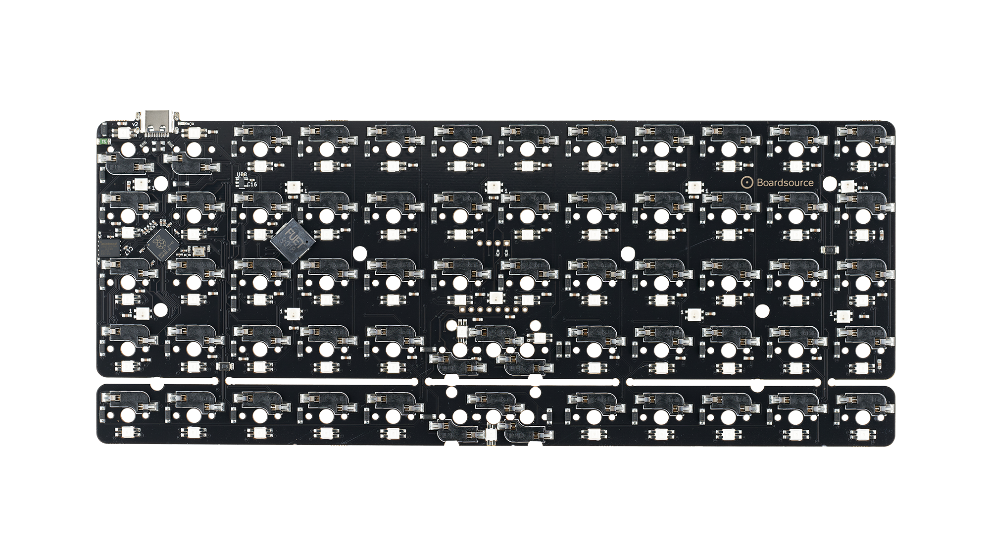
The Equals PCB is designed to be the ultimate ortholinear layout keyboard PCB. Our goal was to create a PCB that will last the test of time and be a great core to your ortho keyboard for years to come. In order to do so we have brought every feature we could think of this PCB, all in a well known and loved layout.
What is 48 and 60?
The numbers after the name are only prevalent in terms of the Equal's keyboard case. They indicate the size of the case, Equals 48 being a 4x12 40% layout and Equals 60 being a 5x12 60% layout. In terms of the PCB, the numbers do not matter. All Equals PCBs start a 5x12 60% layout, and the bottom row can be snapped away to transform it into a 4x12 40% layout. The same PCB goes in either case, the only decision you make is whether the PCB is MX or Choc (LP).
Case compatibility
The Equals PCB is designed to be compatible with the following cases:
- MX
- LP
- Equals 60 lp
- Technik *see notes
Features
Basic Features
these features were also present on the old Technik PCBs
- UBB-C
- Per-key RGB Lighting
- Underglow RGB Lighting
New Features
- RP2040 MCU
- 16mb of ROM
- 2u Spacebar Support
- Piezo Buzzer
- OLED Support (both 32x128 & 64x128)
- 1.8 Inch Full Color 128x160 SPI TFT Screen Support
- Exposed pins for you to hack and utilize however you wish
Pinout
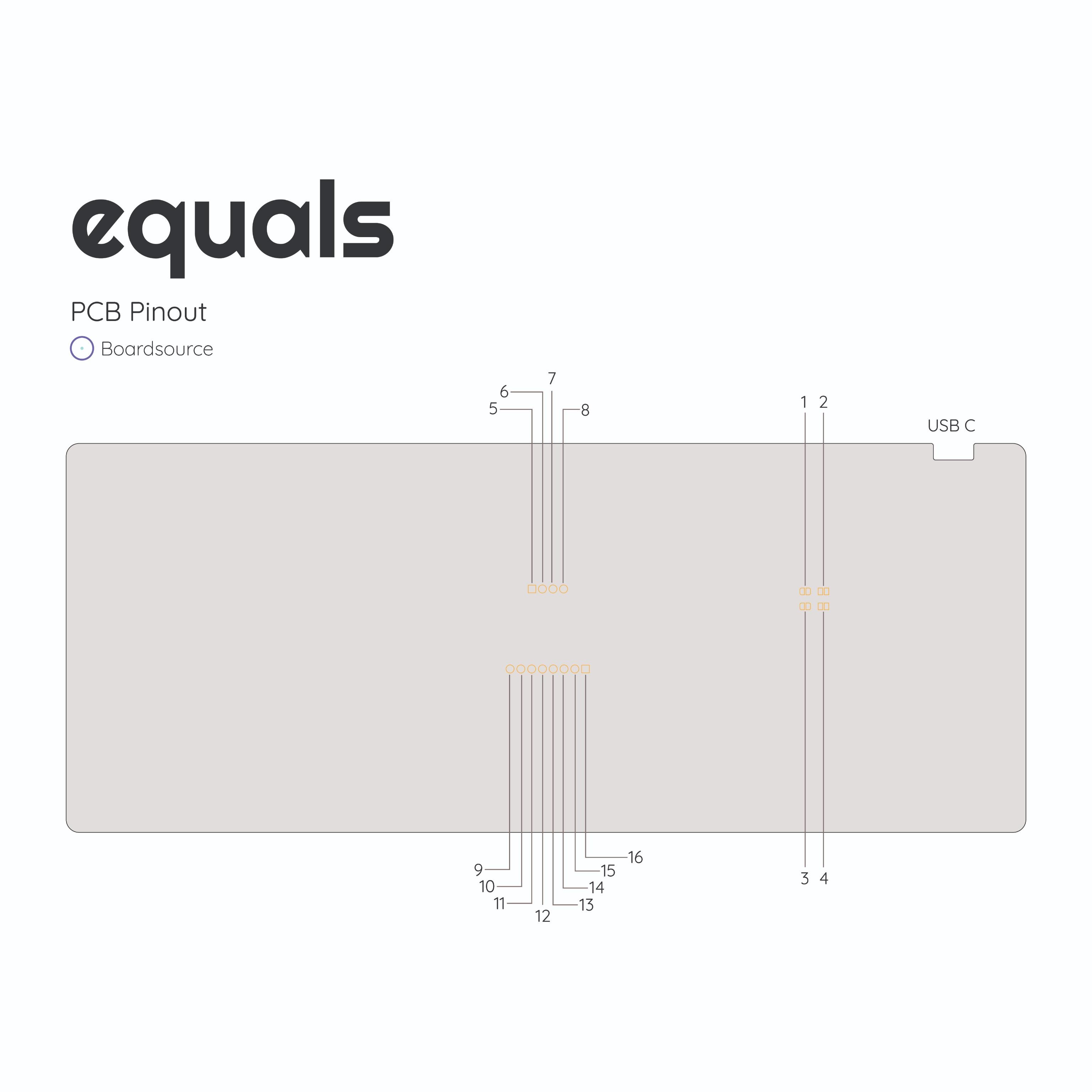
| image key | pin name | python name | function | alt function |
|---|---|---|---|---|
| 1 | RST | NA | reset board | NA |
| 2 | BOOT | NA | UF2 boot mode | NA |
| 3 | BOOT | NA | UF2 boot mode | NA |
| 4 | RST | NA | reset board | NA |
| 5 | gpio22 | SDA | I2c SDA | digital input output |
| 6 | gpio23 | SCL | I2c SCL | digital input output |
| 7 | VCC | NA | 3.3v | NA |
| 8 | GND | NA | GND | NA |
| 9 | VCC | NA | 3.3v | NA |
| 10 | gpio25 | GP25 | SPI CS | digital input output |
| 11 | gpio20 | GP20 | SPI dc | digital input output |
| 12 | gpio28 | GP28 | SPI rx | ADC |
| 13 | gpio27 | GP27 | SPI tx | ADC |
| 14 | gpio26 | GP26 | SPI sck | ADC |
| 15 | VCC | NA | 3.3v | NA |
| 16 | GND | NA | GND | NA |
Not listed in the image
| pin name | python name | function |
|---|---|---|
| gpio0 | TX | col 0 |
| gpio1 | RX | col 1 |
| gpio2 | GP02 | col 2 |
| gpio3 | GP03 | col 3 |
| gpio4 | GP04 | col 4 |
| gpio5 | GP05 | col 5 |
| gpio6 | GP06 | col 6 |
| gpio7 | GP07 | col 7 |
| gpio8 | GP08 | col 8 |
| gpio9 | GP09 | col 9 |
| gpio10 | GP10 | col 10 |
| gpio11 | GP11 | col 11 |
| gpio12 | GP12 | row 0 |
| gpio13 | GP13 | row 1 |
| gpio16 | GP16 | row 2 |
| gpio17 | GP17 | row 3 |
| gpio18 | GP18 | row 4 |
| gpio21 | GP21 | rgb led pin |
| gpio24 | GP24 | status led |
| gpio29 | GP29 | buzzer pin |
Screens
Equals PCB's have two rows of header pins exposed on the PCB, towards the middle of the board. These header pins are exposed to allow users to install either an OLED screen or TFT screen instead of keys. Please note, installing screens on the Equals of course reduces the amount of keys you can use, you sort of convert the PCB into a unique single piece split. Beyond installing a screen these pins were chosen to be used because you now have access to I2C and 3 ADC lines to hack or manipulate however you wish.
Important Notes
When breaking off the bottom row slight trimming may be required to fit into Technik cases. Old Technik plates will not work with the new PCB. You must get an Equals Technik plate.
Image Key (1,2,3,4):If you want to swap the function of the two reset switches on the back of the PCB, you need to cut between the pads 2 and 4 and jump the pads 1 and 3. Standard firmware strategies for resetting your board make Reset Switches unnecessary.