Build Guide
This is the build guide for Corne Cherry v3. Click here for the Corne Cherry v2 build guide.
Parts
Required
| Name | Count | Remarks |
|---|---|---|
| PCB | 1 set | |
| Top plate | 2 sheets | 1.5mm-3mm thick |
| Bottom plate | 2 sheets | |
| OLED cover | 2 sheets | |
| ProMicro | 2 | Alternative: Elite-C |
| TRRS jack | 2 | |
| Reset switch | 2 | |
| Diodes | 42 | SMD Only (SOD-123 Package) |
| PCB sockets | 42 | Compatible with Kailh and Gateron |
| Key switches | 42 | Only compatible with MX style |
| Keycaps | 42 pieces | 1u 40 pcs, 1.5u 2 pcs |
| Spacer M2 7.5mm | 10 pieces | For Case assembly |
| Spacer M2 9mm | 4 pieces | For OLED cover |
| Screw M2 4mm | 28 screws | |
| Rubber feet | 8 pieces | |
| TRRS (4 poles) cable | 1 | TRS (3 poles) cable is also compatible |
| Micro USB cable | 1 | Avoid charge-only cables |
Optional
| Name | Count | Remarks |
|---|---|---|
| OLED module | 2 | |
| SK6812MINI-E | 42 | LEDs for Backlight |
| WS2812B | 12 | LEDs for Undergrow |
| Microcontroller/OLED Sockets | 1 | Alternative: 2.54 1row femal sliv option |
| Microcontroller Pins | 48 | Alternative: Diode/Resistor legs |
| OLED Headers | 1 | Soldered to OLED module |
Firmware preparation
If you build the firmware yourself, it will take some time to set up the environment, so it's best to start at the beginning.\ It is recommended to flash ProMicro's prior to soldering.\ For more information, please see firmware.
Verification
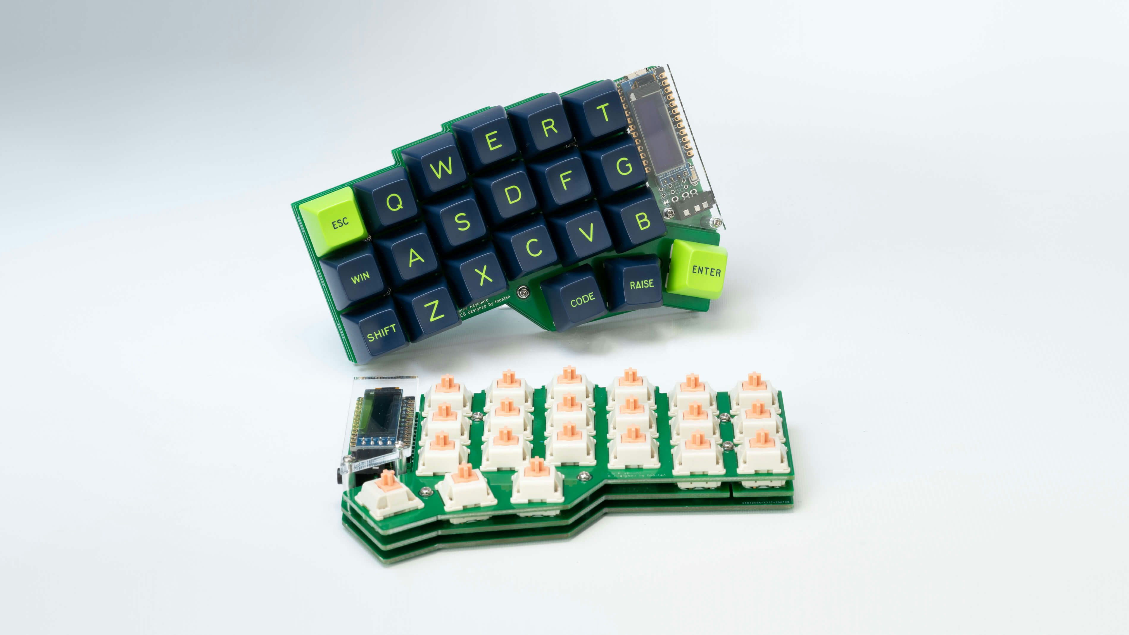
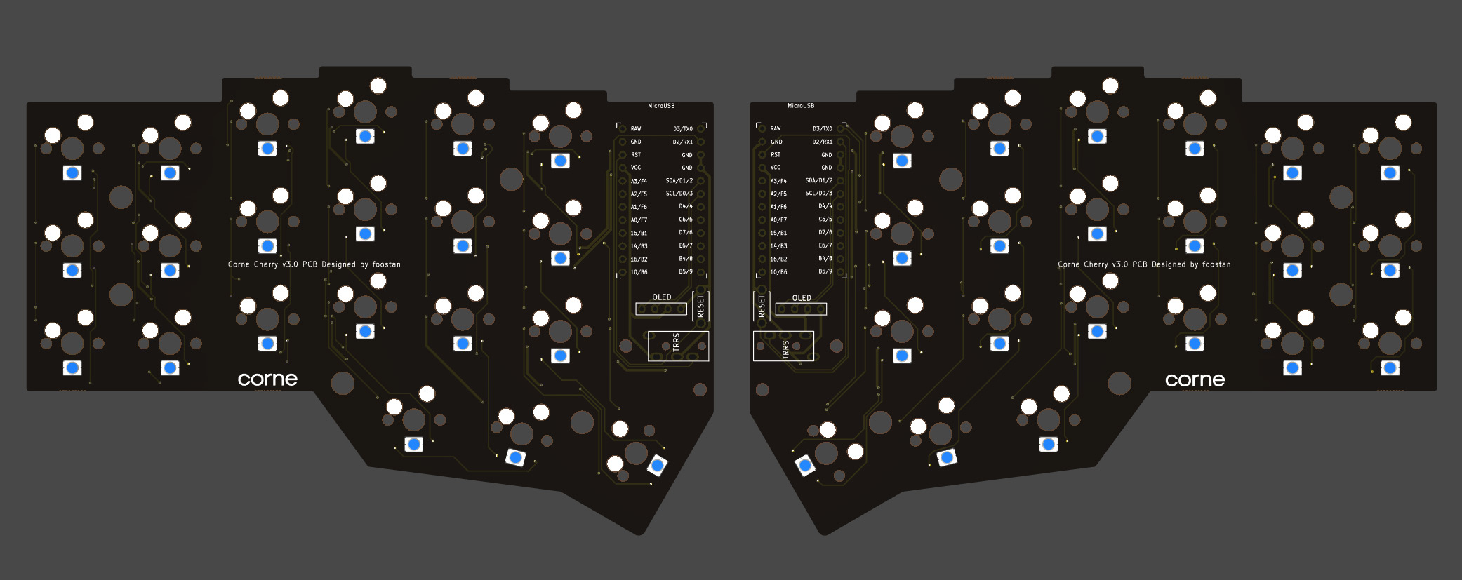
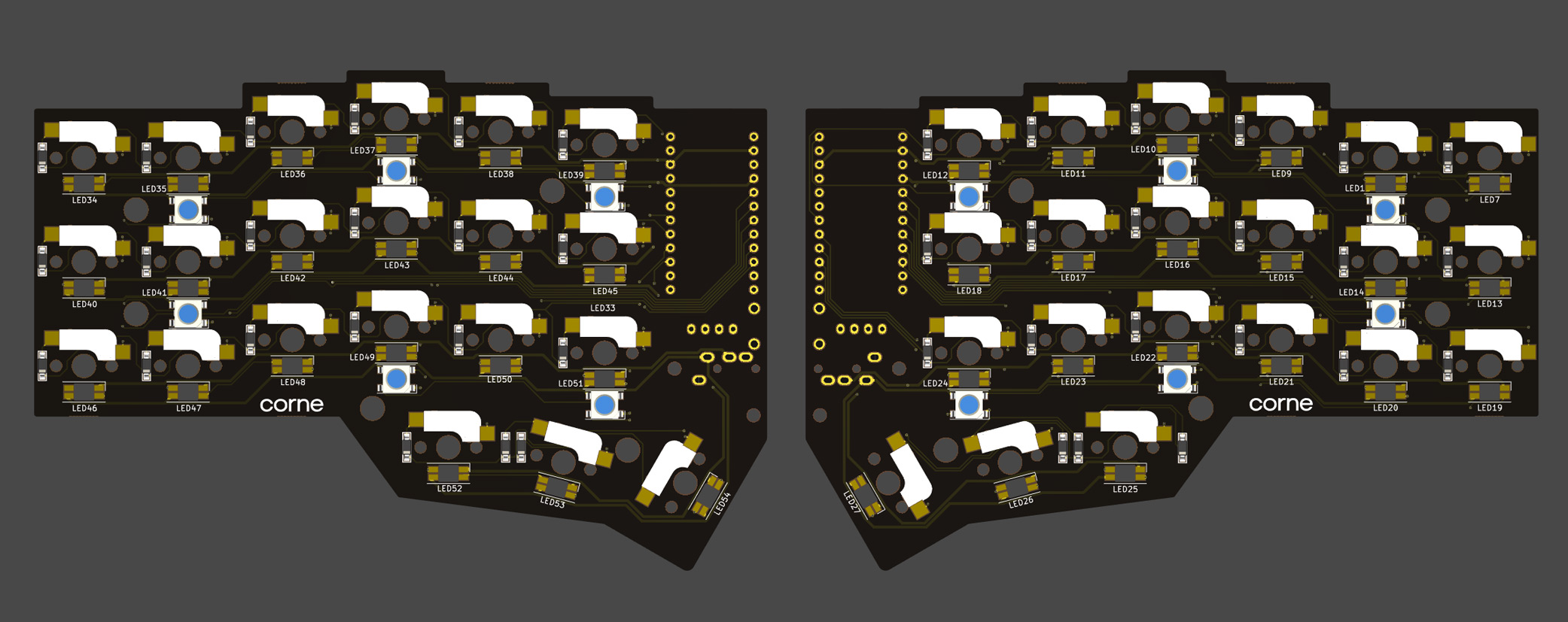
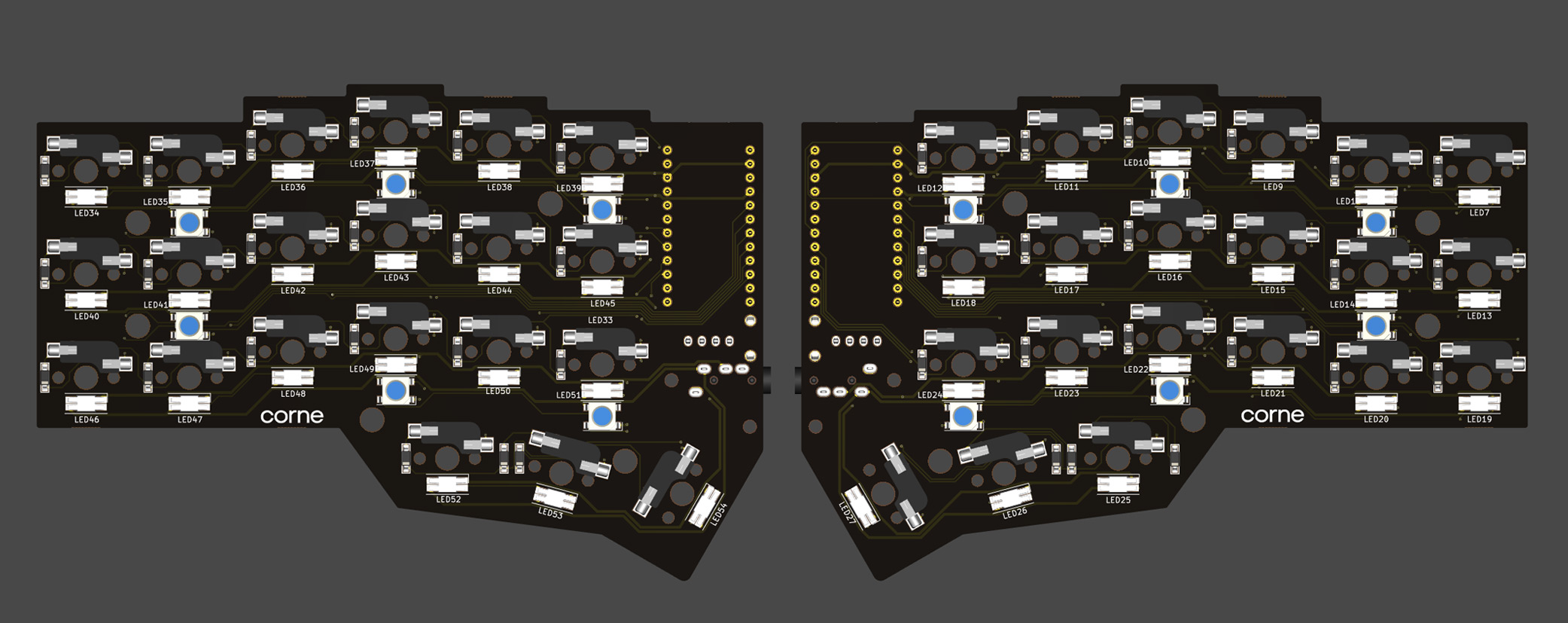
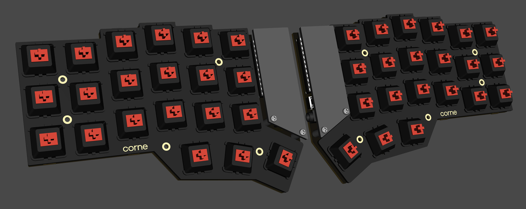
The PCB for Corne Cherry v3 is as follows. Make sure it is the same as your PCB.
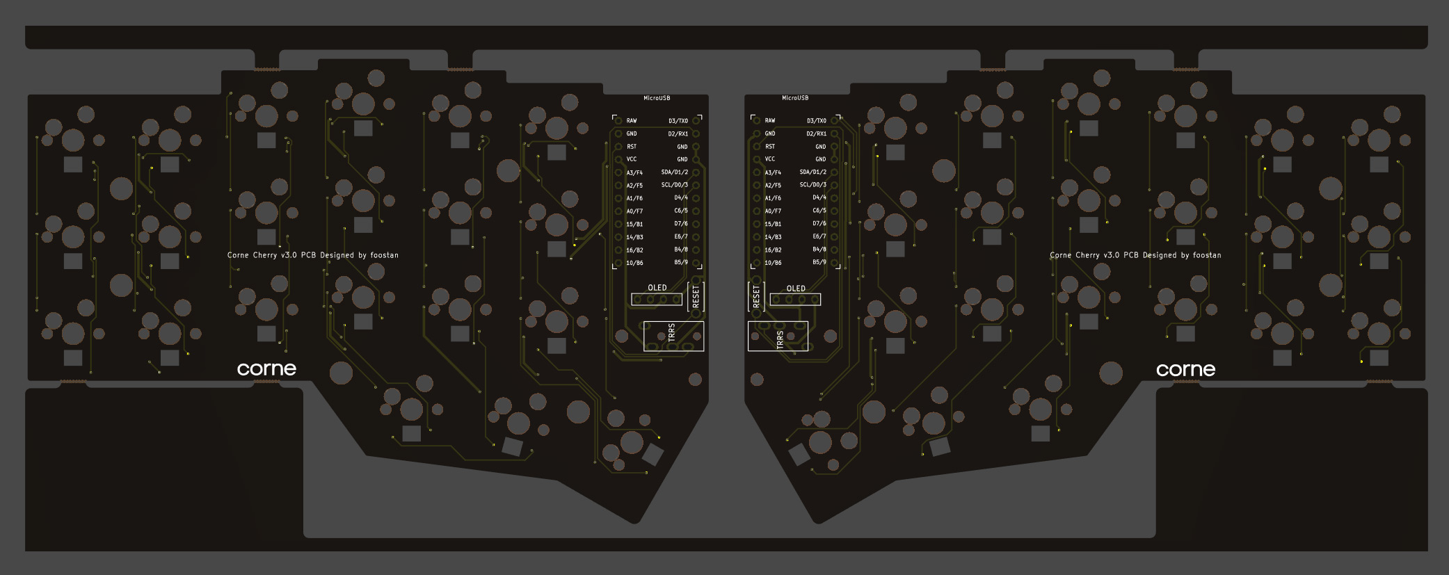

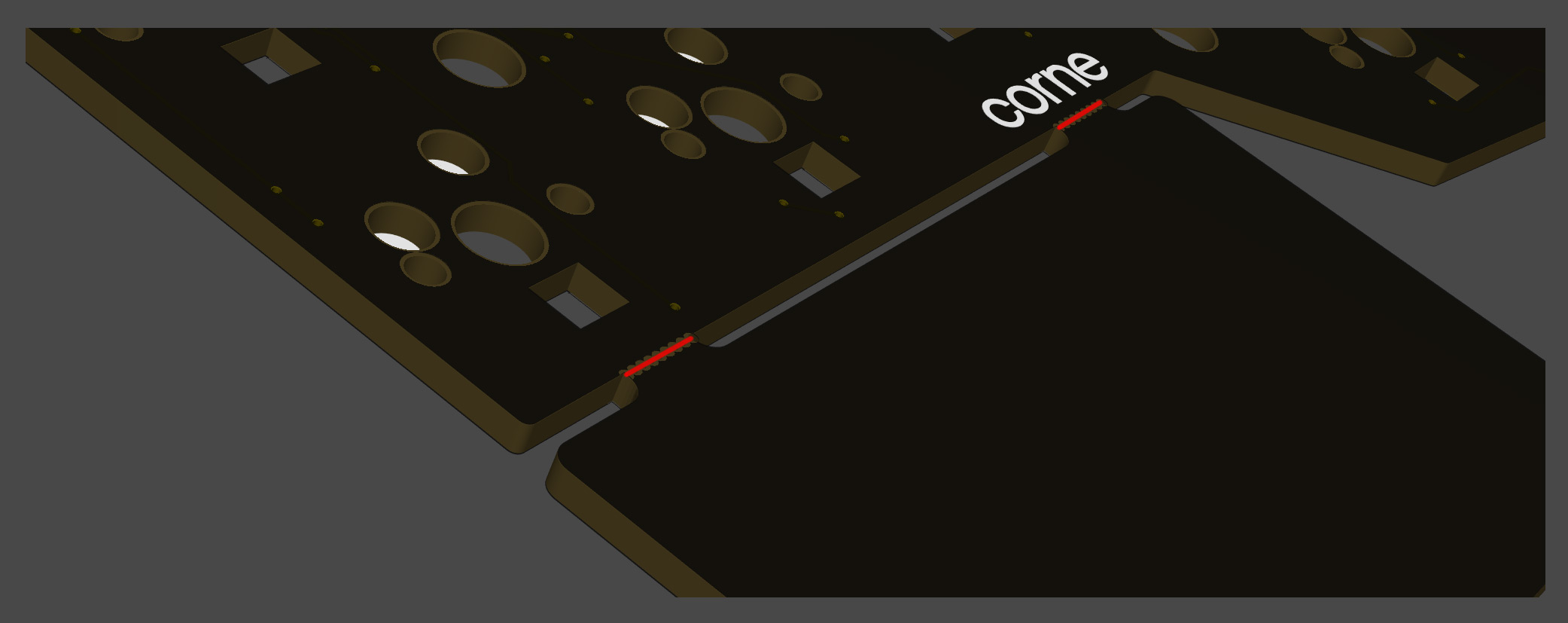
The PCB comes with a frame for manufacturing reasons. You can fold it by hand to remove it, but if it is difficult, make a cut in the joint* with a cutter or similar, to make it easier to remove. In addition, the joint can be cleaned with a file.
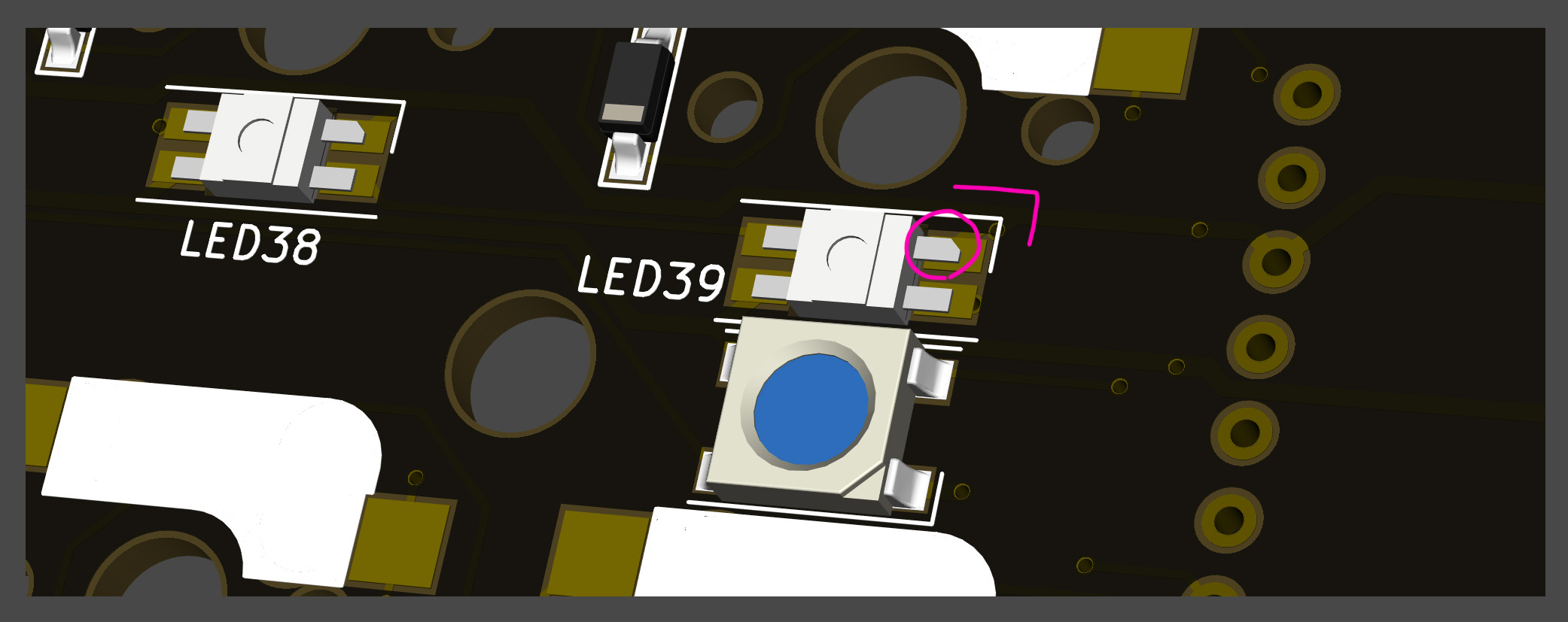
*Joint part: There are a total of 8 parts, which are marked in red in the image below.
Assembly
Diodes
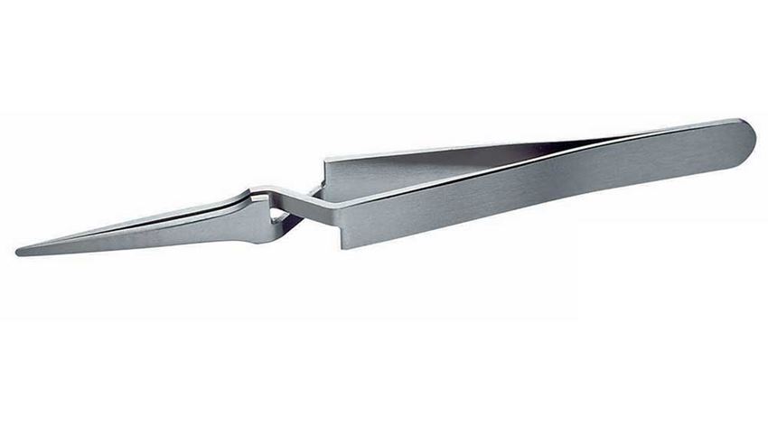
Since SMD parts are very small, fine-tip/reverse-action tweezers are recommended.
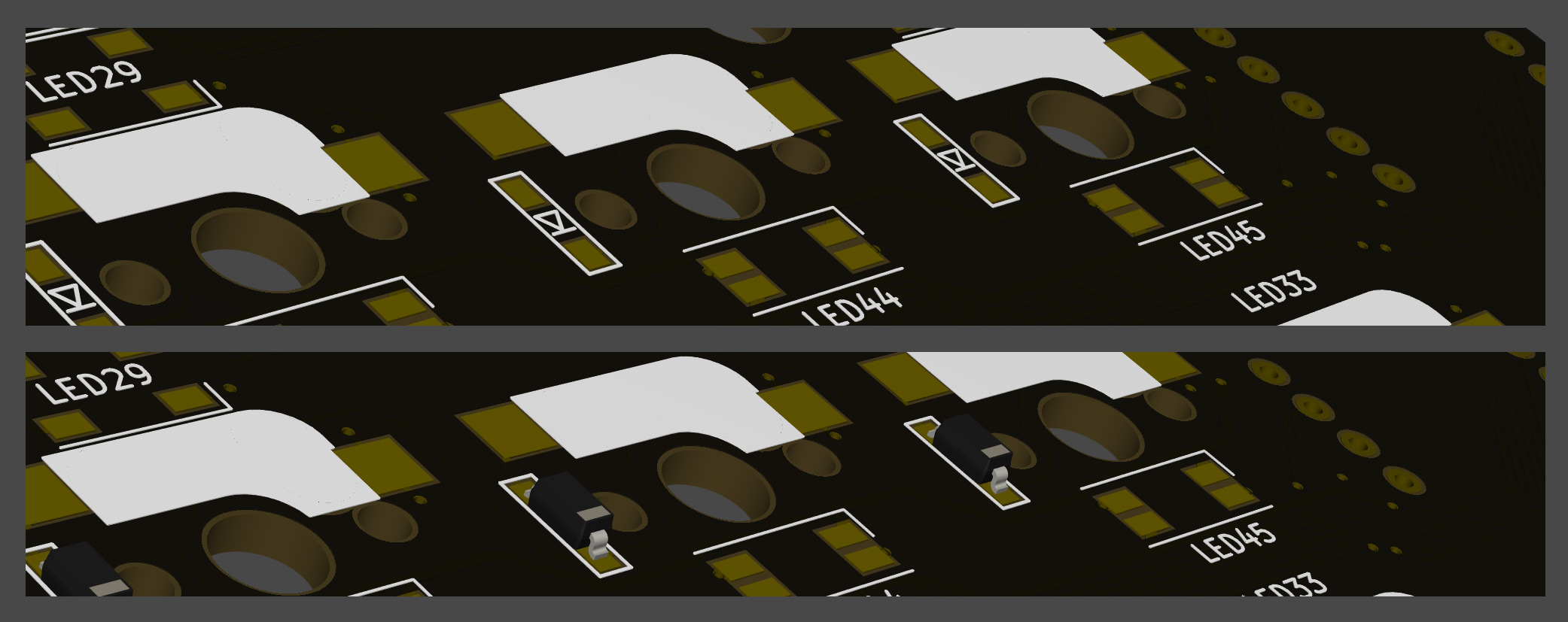
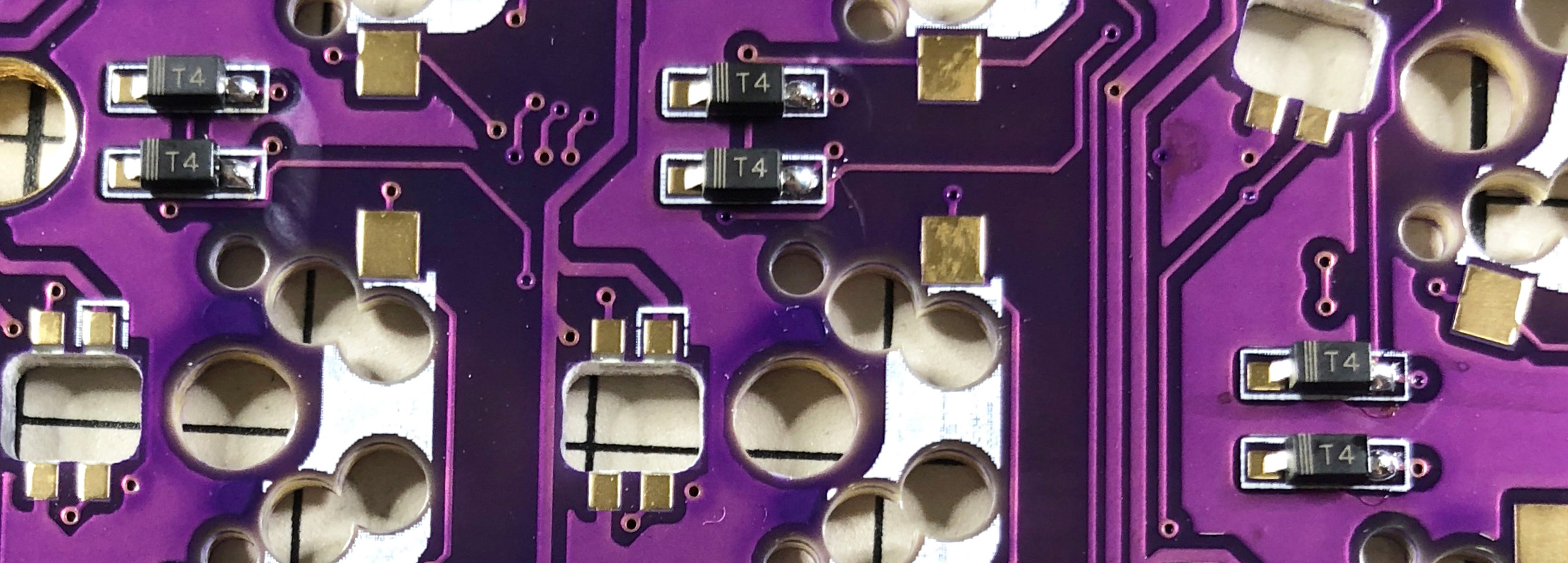
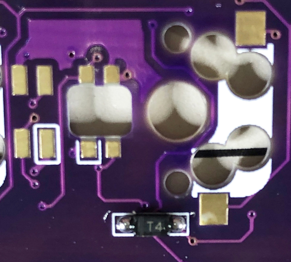
The diodes have a specific orientation, so install with "|" marking on the diode facing the "|" on the PCB marking: "|◁"
 TIPS: Tips for installing SMD parts
Begin with applying solder to only one pad.

Next, place SMD component while heating solder. At this time, it is recommended to use reverse-action tweezers, so that you can hold the SMD part firmly without applying force, and concentrate on alignment and soldering instead. Also, if the soldering iron is too hot or the solder is touched too long, the flux contained in the solder may evaporate and form a poor solder joint, but it can be repaired later, so at this point you should only care about attaching parts. It's okay.
It is okay if the SMD component is not flush with the PCB when viewed from the side. If it is floating, press the SMD component down with tweezers or your finger and reheat the solder.
Then solder the other contacts. Be careful not to apply too much solder, as a small amount is sufficient. If you have applied too much, you can remove it with a suction pump, solder wick, or by picking it up with a soldering iron.
If the amount of solder on the preliminary solder side is small, additional soldering is performed, and if it is a heap, apply flux from above and heat it to clean it.
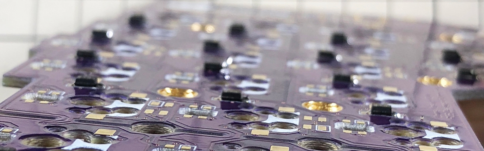
The diode is completed by soldering 42 pieces in total on the left and right.
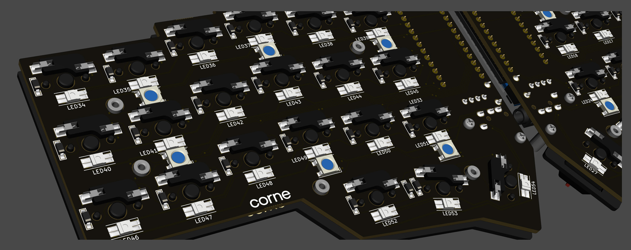
LED (optional)
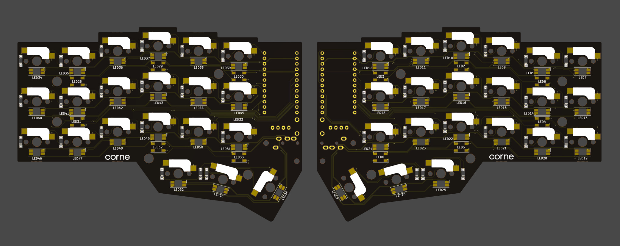
Solder the SK6812MINI-E and WS2812B.
All soldering is done from the back side, but the SK6812MINI-E is for Backlight (the front side is shining) and the WS2812B is for Undergrow (the back side is shining).
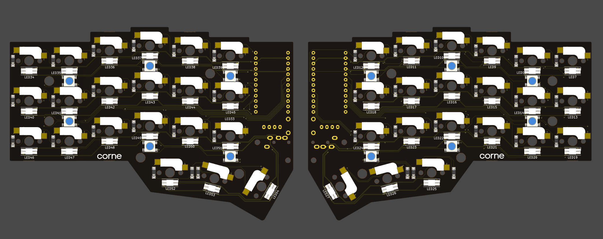
WS2812B (Undergrow)
First, solder the WS2812B.
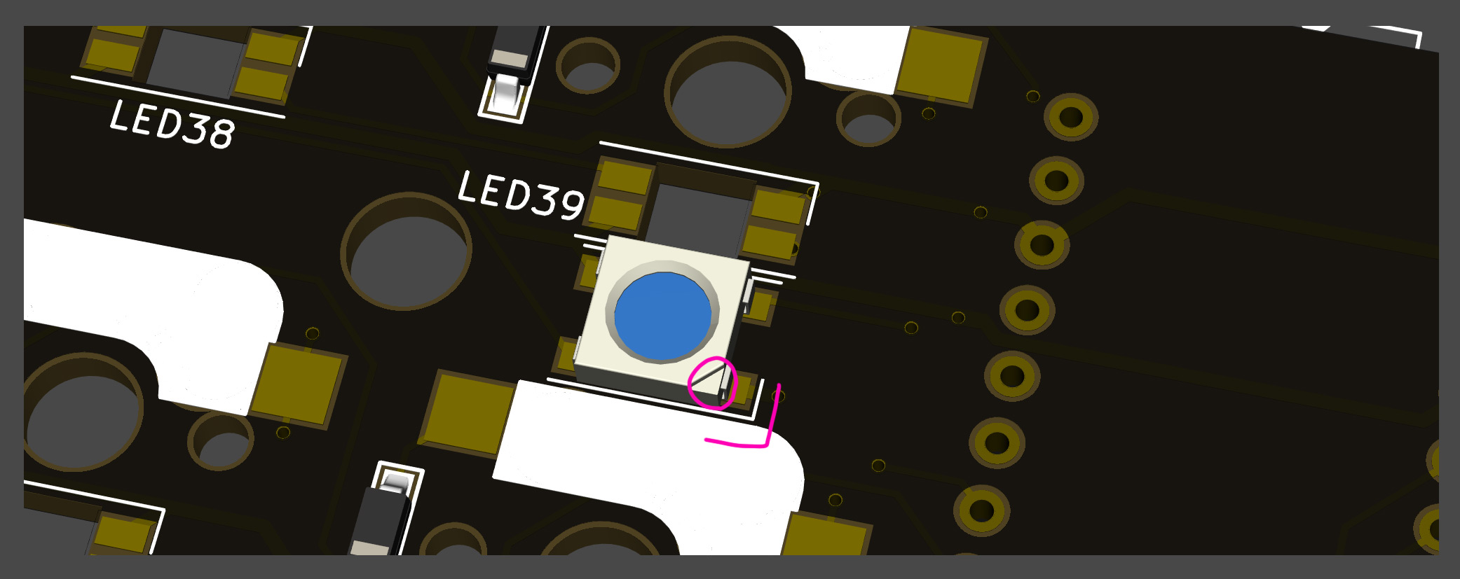
Match recessed corner of the LED with marked corner on the PCB as shown below. Refer to TIPS: Tips for installing SMD parts section above as similar soldering procedure is followed.
WS2812B LED soldering is completed after 12 are installed on left and right.
SK6812MINI-E (Backlight)
Then solder the SK6812MINI-E.
Match the notched corner of the LED with the marked corner on the PCB as show below. Refer to TIPS: Tips for installing SMD parts section above as similar soldering procedure is followed. These are more resilient than the SK6812MINI LEDs, but still may be damaged if directly exposed to the heat of a soldering iron. ~320°C seems to be an ok temperature, evne if all four legs are soldered one after another.
SK6812MINI-E LED soldering is completed after 42 are installed on left and right.
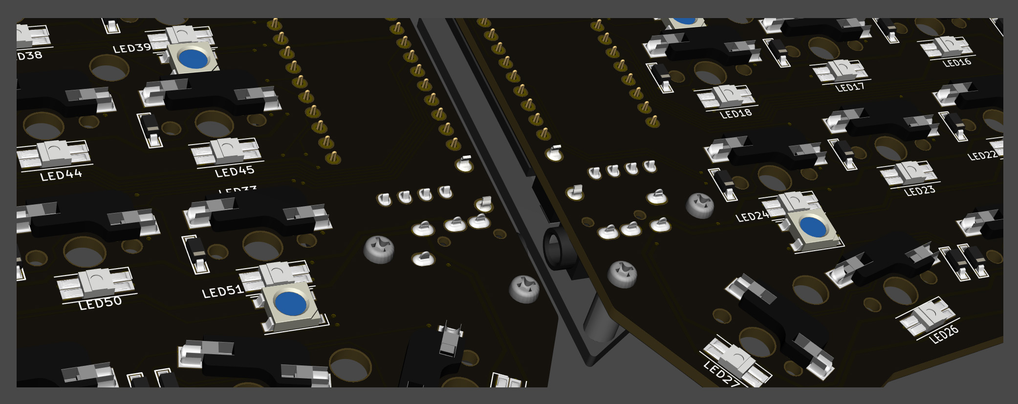
TRRS jack, reset switch, pin socket for OLED
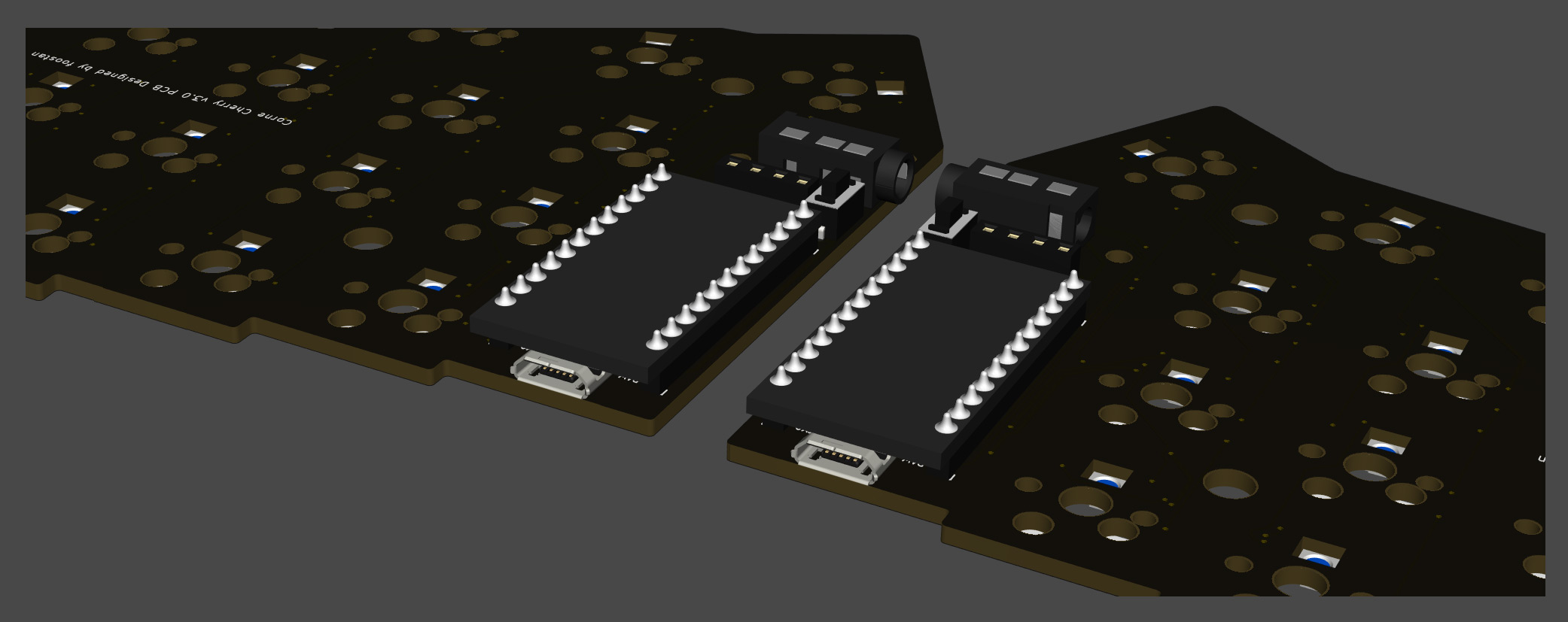
Solder the TRRS jack, reset switch (tact switch), and OLED pin socket as shown in the picture below.

Since these parts may fall off when soldering, you can affix them with masking tape.
ProMicro
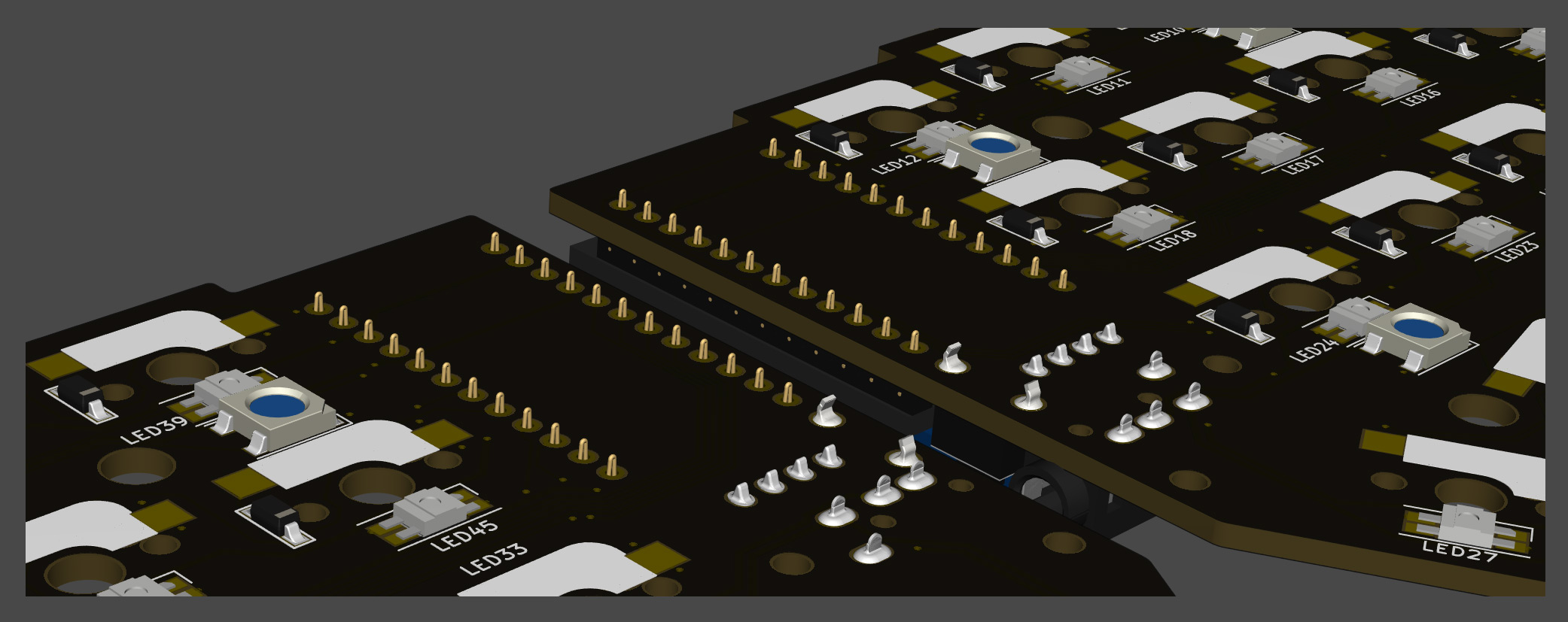
Solder headers to PCB. Then solder ProMicro to headers, with components facing PCB as shown below.
If you use spring-loaded pin headers, you do not need to solder the back side. Please refer to the Helix Build Guide for details on how to use spring-loaded pin headers.
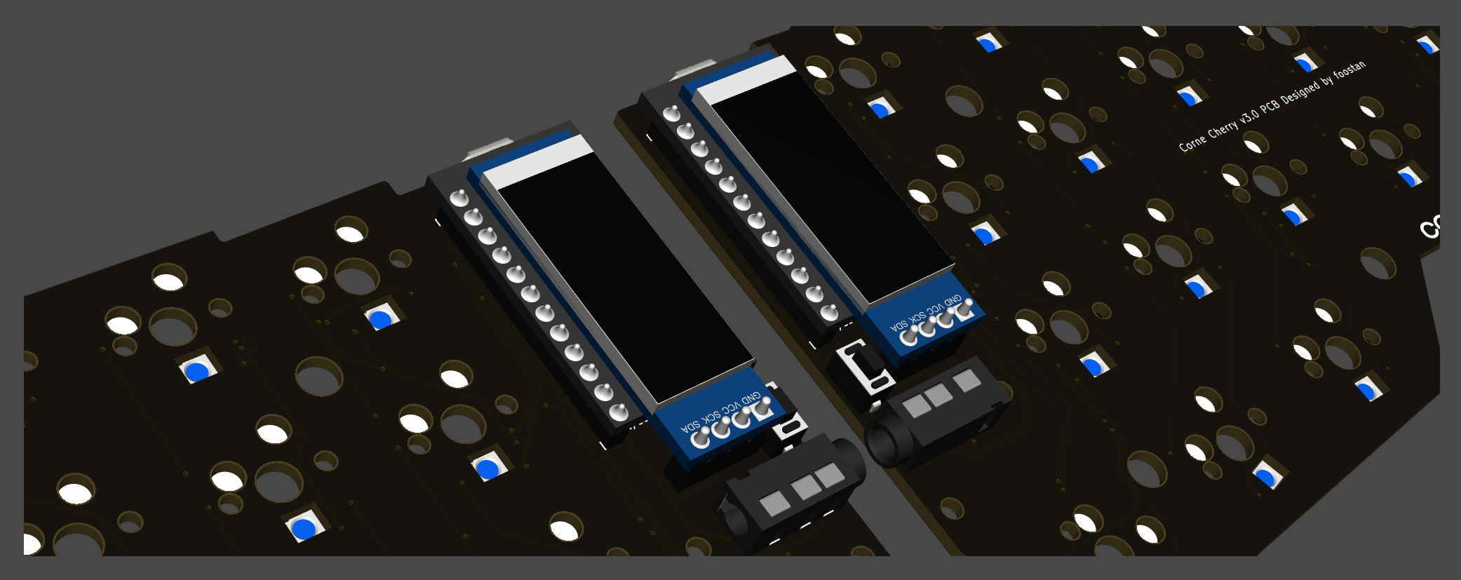
OLED module
Insert the pin header into the socket first, then solder the OLED module to the pin header. Note: Solder one pin to OLED module, then reheat solder to confirm OLED module is level, then solder remaining pins.
Operation check
Now is a good time to test your keyboard to help isolate potential problems.
To check the operation, connect left and right sides with TRRS cable, then connect left side to the computer with USB cable. If it is done correctly so far, shorting a hotswap socket pad with tweezers will output out a keypress and it will be displayed on the OLED module.
Switch Sockets
Solder hotswap sockets according to mark on PCB as shown below. Refer to TIPS: Tips for installing SMD parts section above as similar soldering procedure is followed.

Switch Socket soldering is completed after 42 are installed on left and right.
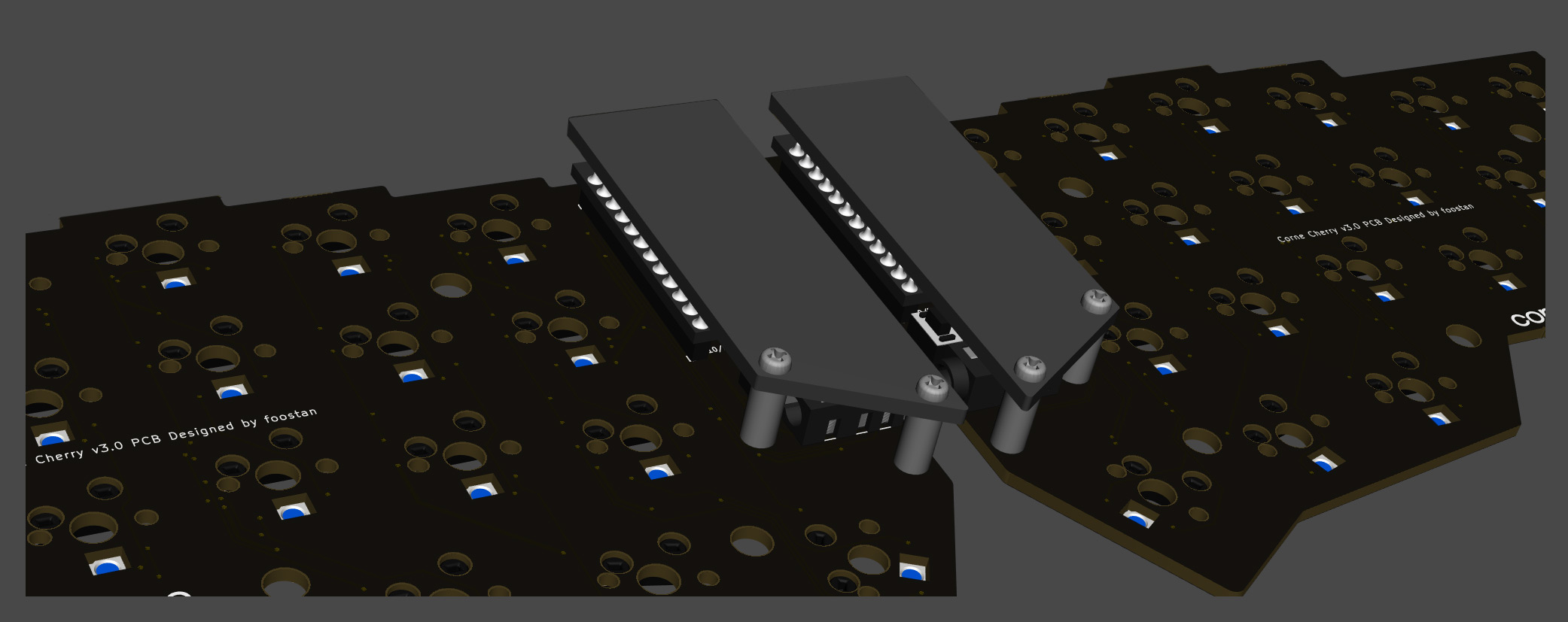
OLED protective cover
Attach the OLED protective cover with M2 9mm spacers and M2 screws.
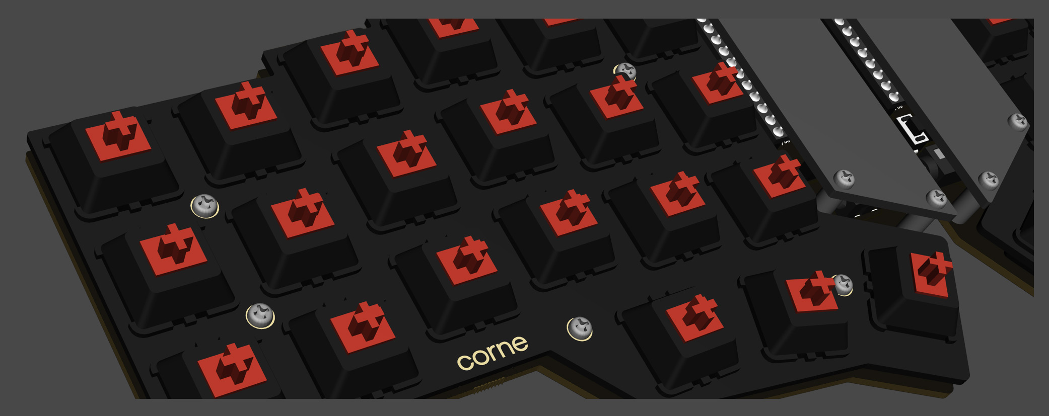
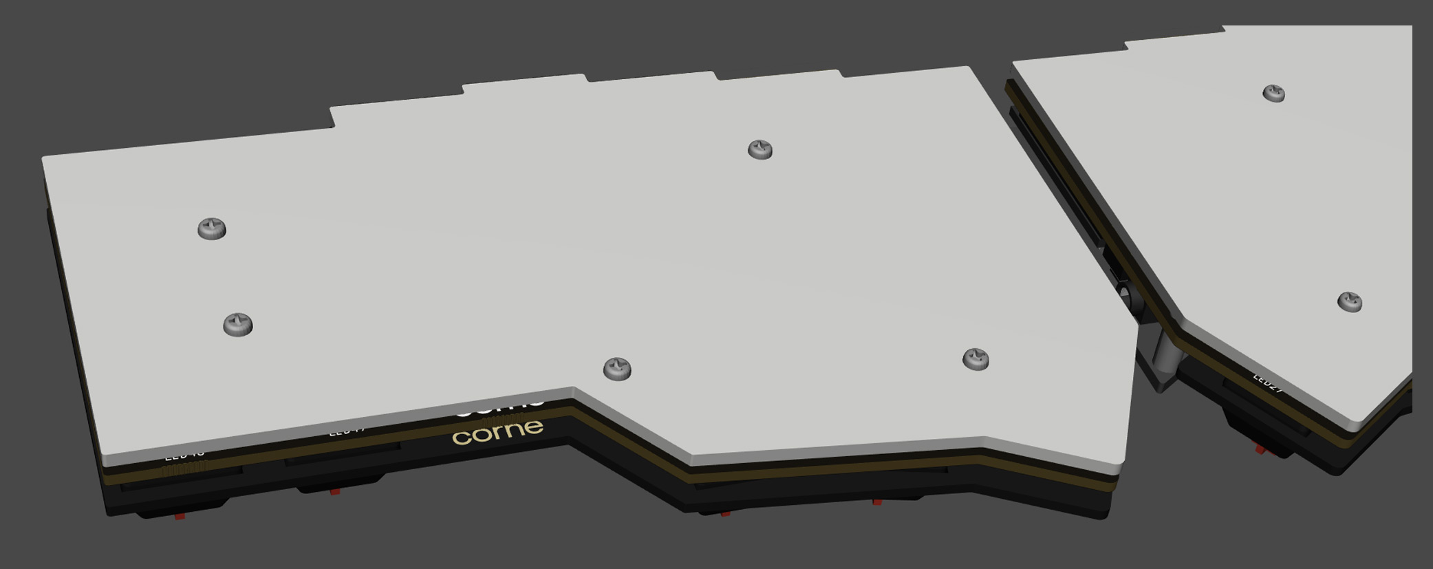
Plates & Switches
Place a few key switches into the top plate, then line up and press into PCB socket. If you attach all the key switches to the top plate first, it will be more difficult to fit them in the PCB sockets all at once. So it is recommended to do a few to begin with.
Install the M2 7.5mm spacer and M2 screws on the top plate.
It is easy to screw the spacer in after inserting it into the hole from the back side.
Attach the bottom plate with M2 screws.
Install the rubber feet in the following positions.

That's it!
Firmware
QMK
In qmk this keyboard can be found under crkbd. To begin, follow the QMK setup guide. (if working from an existing installation, an update may be needed.) \ For flashing instructions, see doc or video
KMK / PEG
In Peg or KMK this keyboard can be found under crkbd
Peg can be downloaded here, and the quick start can be seen here.
For Kmk can be downloaded here and the quick start can be seen here
Here are some links to other articles that may help you get the most out of your new keyboard:
- Get the most out of your PCB Unleashing the High-Tech Power of Custom Keyboards
- Keyboard Programing
Extra
For questions, ask in Boardsource Discord server